Master Xenon Light Fastness Testing: Step-by-Step Chamber Guide for Accurate Results
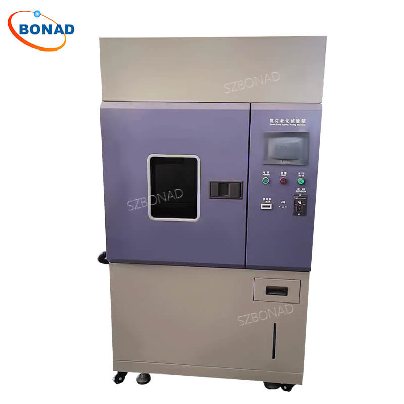
Ensuring materials retain their color, integrity, and performance under sunlight and environmental stress is paramount across industries like textiles, plastics, automotive, and coatings. The xenon light fastness chamber (or xenon arc weatherometer) is the industry-standard instrument for simulating these damaging conditions in a controlled laboratory environment. Proper operation is crucial for generating reliable, repeatable data. This step-by-step guide walks you through the essential process for using a xenon light fastness chamber effectively.
Preparation and Safety Checks: The Critical First Step
Before initiating any test, thorough preparation and safety protocols are non-negotiable for both operator safety and test integrity.
- Chamber Inspection: Visually examine the chamber for any signs of damage, especially to the xenon lamp, quartz filters, cooling system, spray nozzles, and sample holders. Ensure the interior is clean and free of dust or debris that could obstruct light or contaminate samples.
- Safety First: Strictly adhere to the manufacturer’s safety guidelines. Xenon lamps emit intense UV radiation – never look directly at the lamp when operating. Always wear appropriate personal protective equipment (PPE), including UV-protective safety glasses and gloves, when handling samples or chamber components.
- System Check: Verify that all chamber systems (cooling water, air supply if used, drain) are connected, functioning correctly, and meet the manufacturer’s specifications.
Calibration: Ensuring Accuracy from the Start
Regular calibration is fundamental for the xenon light fastness chamber to accurately replicate real-world conditions. Skipping this step risks invalid data.
- Lamp Verification: Confirm the xenon lamp is within its operational lifespan. Aging lamps lose intensity and shift spectral output.
- Radiometer Calibration: Calibrate the chamber’s radiometer (light intensity sensor) according to the manufacturer’s schedule and procedures. This ensures precise control and measurement of irradiance levels (usually in W/m² @ specific wavelengths like 340nm or 420nm).
- Sensor Accuracy: Calibrate temperature and relative humidity sensors using traceable standards. Verify chamber uniformity across the sample plane for temperature and humidity.
- Spectral Filters: Ensure the correct optical filters (e.g., Daylight, Window Glass) are installed, clean, and within their recommended replacement interval. Filters degrade and alter the light spectrum.
Preparing and Mounting Test Samples: Consistency is Key
How samples are prepared and mounted directly impacts test uniformity and results.
- Sample Preparation: Cut samples to the precise size required by your test standard (e.g., ASTM G155, ISO 105-B02, AATCC TM16) or internal protocol. Ensure samples are representative, defect-free, and consistently sized. Label each sample clearly for identification.
- Mounting Securely: Use the chamber’s designated sample holders or frames. Mount samples flat and taut, without wrinkles, folds, or sagging. Uneven tension or surface exposure leads to inconsistent degradation and unreliable results.
- Positioning & Rotation: Place samples according to the test standard’s requirements regarding distance from the lamp and potential rotation patterns. If testing multiple materials, document their exact positions within the rack. Ensure holders are clean and corrosion-free.
Configuring Test Parameters: Mimicking Real-World Stress
Accurate simulation hinges on setting the correct environmental parameters.
- Select Test Standard: Base your parameters on an established standard (e.g., ASTM G155 Cycle 1 for general outdoor, ISO 4892-2, AATCC TM16 Option 3) or a validated internal protocol relevant to your material’s end-use.
- Key Parameters:
- Irradiance Level: Set the target irradiance (e.g., 0.35, 0.55, or 0.80 W/m² @ 340nm) and wavelength control.
- Chamber Temperature (Black Panel/Standard): Define the dry bulb temperature.
- Relative Humidity: Set the target humidity level during light phases.
- Cycle Definition: Program light/dark cycles, spray cycles (duration, frequency), and dark phase humidity/temperature if applicable.
- Test Duration: Set the total exposure time (hours) or the target radiant energy dose (kJ/m²).
- Double-Check Settings: Meticulously verify all programmed parameters before starting the test. Ensure they align completely with the chosen standard or protocol.
Running the Test and Monitoring: Vigilance for Validity
Initiate the test only after confirming all preparations are complete.
- Continuous Monitoring: Regularly check the chamber’s control panel or software interface to ensure all parameters (irradiance, temperature, humidity) remain stable and within the specified tolerances. Note any deviations immediately.
- Alarm Systems: Utilize the chamber’s built-in alarm systems for parameter deviations or system failures (e.g., low water, lamp failure). Respond promptly to any alarms.
- Documentation: Maintain a detailed logbook. Record start time, initial parameter settings, any adjustments made during the test, alarm events, and general observations. Consistent documentation is vital for traceability and troubleshooting.
- Avoid Unnecessary Interruptions: Minimize opening the chamber door during light phases to maintain stable conditions and prevent spectral distortion.
Analyzing Results and Post-Test Protocol
Completing the exposure is just the beginning; rigorous analysis and chamber care follow.
- Sample Removal & Conditioning: Carefully remove samples according to the test standard. Most standards require conditioning samples under controlled temperature and humidity (e.g., 21°C ±1°C, 65% ±2% RH) for 24 hours before evaluation to stabilize them.
- Evaluation: Assess samples for:
- Color Change: Use a spectrophotometer and color matching software (e.g., CIELAB ΔE, ΔL, Δa, Δb) to quantify fading or color shift against unexposed controls. Utilize visual grayscale ratings (e.g., ISO Grey Scale, AATCC Chromatic Transference Scale).
- Physical Changes: Inspect for surface degradation like cracking, chalking, blistering, loss of gloss, embrittlement, or changes in texture. Document findings thoroughly with photographs.
- Data Interpretation: Compare results to acceptance criteria, previous batches, competitor materials, or baseline performance requirements. Generate a clear test report.
- Chamber Maintenance:
- Clean the chamber interior, sample holders, and spray nozzles thoroughly.
- Replace water in reservoirs with fresh deionized or distilled water as specified.
- Perform any minor maintenance tasks recommended by the manufacturer post-test.
- Document maintenance performed.
By meticulously following this structured approach to using your xenon light fastness chamber, you significantly enhance the accuracy, reliability, and repeatability of your material durability and colorfastness testing, providing critical data for product development and quality assurance.